
Fiber Tools for Fiber Lovers
-
Product on sale
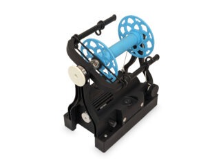 EEW 6.1Original price was: $299.00.$269.00Current price is: $269.00.
 -
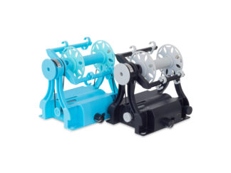 EEW Nano 2$125.00
 -
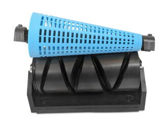 EEW Cone Winder$259.00
 -
 EEW Yarn Counter$65.00
 -
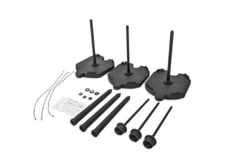 EEW Lazy Kate$34.00
The Electric Eel Wheel (EEW) 6.1 is the ultimate eSpinner for fiber enthusiasts. It allows you to transform animal and plant fibers into beautiful handspun yarn on its large 8 ounce bobbins. It is our fastest and quietest spinning wheel to date. The precision-machined steel spindle and ball bearings ensure a vibration-free spinning experience. The lightweight and compact design makes it perfect for on-the-go spinning, while the reinforced nylon case ensures durability for even the most demanding production workloads. The EEW 6.1 product page contains additional information and useful videos.
The EEW Nano 2 is the lower-priced and more compact cousin of the EEW 6.1. With its 2 ounce bobbins and the ability to power it from a USB port, it is the ultimate travel-friendly wheel. Traditional spinning wheels can be expensive. Drop spindles can be slow and difficult to learn. But, the EEW Nano offers an affordable and easy-to-use option for all skill levels. With its fully functional design, you can spin singles and ply them together effortlessly. The EEW Nano 2 product page contains additional information and useful videos.
The EEW Cone Winder is a motorized cone winder that automatically and evenly places yarn onto cones. It can take balls or skeins of yarn and put them onto cones. The cones can hold over a pound of yarn. The EEW Cone Winder product page contains additional information and useful videos.
The EEW Yarn Counter is the ultimate yarn measuring tool for fiber artists. This precision instrument is designed for knitters, crocheters, spinners, weavers, and anyone who uses yarn. With its accurate, versatile, and affordable features, it is a must-have for anyone who wants to keep track of their yarn stash. The EEW Yarn Counter product page contains additional information and useful videos.
The EEW Lazy Kate holds bobbins while you ply them together. It comes with a clever puzzle shaped system to lock themtogether and magnets to keep everything in place. The EEW Lazy Kate product page contains additional information and useful videos.

The EEW tools thrive thanks to the dedicated community that surrounds it. Without your valuable feedback, the EEW would not be what it is today. With over 27,000 members on our EEW Ravelry Group, EEW Facebook Group, and YouTube Channel, these are great resources for any questions or concerns regarding your EEW.
Stay informed and connected by subscribing to our newsletter and following us on your preferred social networking platforms using the links at the bottom of this page. If you have any questions please contact us. We are here to help find the perfect fiber tools for your needs.
Happy Spinning!
-Maurice Ribble (Inventor and Founder)